Finite element analysis of a tube swaging process
페이지 정보
작성일posted onLink
본문
Finite
element analysis of a tube swaging process
Swaging process is a metal forming process for manufacturing various mechanical parts by changing cross-sections of rods, tubes and wires [1-10]. There are several advantages of the swaging. First, it is advantageous in mass producing straight or tapered metal shapes with various cross-sections including circle, square, gear and the like. Second, the swaging machine is not only cheap and structurally simple but it is also so easy to operate that it can be run by beginner. Third, the swaging process can remove the generation of chip and thus it is effective in saving material. Of course, it can be applied to various metals at either room or elevated temperature. Fourth, the swaging process enhances both mechanical properties of material including elastic limit, tensile strength, compressive strength and bending strength owing to good fibrous structure of material. Fifth, the swaging process can give excellent surface roughness that cannot be achieved by material removal process and the like.
Swaging has been studied mainly by experimental approaches [1-10]. Of course, most swaging processes have been developed empirically. Due to their kinematical and mechanical complexity, empirical approach to swaging process design inevitably accompanies more or less trial and errors. To solve the problem, several researchers have studied various swaging processes using finite element method [11-14]. Piela [11] and Grosman and Piela [12] suggested two-dimensional approaches to save computational time. The other researchers employed commercialized software for their application-oriented research. However, most previous researches lack in validating their approaches.
Swaging is very complicated from standpoint of both mechanics of process and mechanism of machine. Swaging is one of incremental metal forming technologies which inevitably requires a great deal of computational time. Thus, a proper analysis model is essential to solve the above problems that are inherent in swaging. In this post, an analysis model is presented and applied to simulate a round-to-round swaging process to verify the approach with the new analysis model.
Analysis
model of swaging:
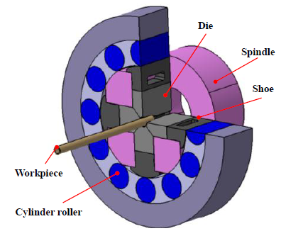
Fig. 1 shows a schematic diagram of a typical swaging process. Swaging process is composed of inner race spindle, outer race spindle, rollers and dies. Relative motion at the interface between rollers and dies which causes from the curved surface carved in the dies’ back surface is major source of power to form the material. The relative motion can be calculated from the geometry of dies. It is noted that the forming dies impose some back-pressing forces on the material when the faces of forming dies are inclined.
For the sake of simplicity, the die motion, which is usually periodical, was thus assumed known in the analysis model in which the swaging process consists of material, forming dies and spring attached pusher as shown in Fig. 2. In the analysis model, the material rotates and translates for being fed in the periodical way and the forming dies translate in the same way. The pusher can feed the material when the material contacts only the pusher. However, it should be noted that the pusher with a spring is a special tool for absorbing the back-pressing force imposed on the material by the forming dies and that its motion is determined by the balance of the back-pressing force and the spring force. The spring force is an input that is a function of backward displacement from the initial contact to current position. Note that the constantly pushing force can be dealt with by a preload of the spring attached on the pusher. In real situations the forming dies may rotate but their rotational motion is replaced by the motion of material for the analysis model. Of course, the relative motion of all objects in the analysis model to the rotating dies should be maintained. The effect of acceleration was neglected, and the material is rigid-plastic and obeys von Mises yield criterion and its associated flow rule.
Application to round-to-round swaging:
Note that it is impossible to simulate the process if the pusher does not support the material and that the fixed boundary condition can cause internal or external bulging of material [14] since the forming dies have quite steep slope.The details of the simulation are described in [16].
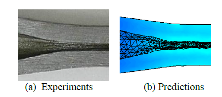
AFDEX 3D was used for the simulation. The number of tetrahedral elements was controlled about 50000~100000. After about 50000 solution steps, the predictions were obtained. Fig. 5 shows the history of deformation. Detailed investigation into the sectional view in Fig. 5(b) shows that the front side of the swaged part is more or less inclined due to the variation of tube thickness while the variation of tube thickness of the swaged part except the front inclined region is negligible. This phenomenon was the same as the experiments made by Lim and his co-workers [8] as seen in Fig. 6. The predicted tube thickness in the non-inclined swaged region ranges from 3.66mm to 3.84mm while its associated experimental tube thickness is about 3.75mm. It is also interesting to note that the wrinkled inner surfaces are observed in both the experiments and predictions. Consequently, it can be concluded that the present approach reflects the real situations quite well.
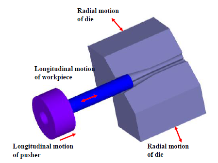
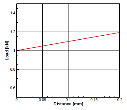
Figure 4. Back-pressing force exerted by the pusher with the movement of the back end of the workpiece
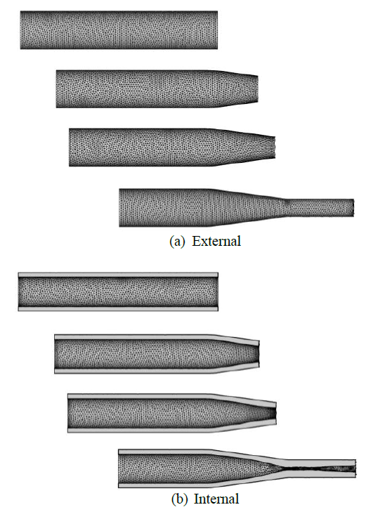
Figure 5. Deformation history
Figure
6. Comparison of experiments[8] and predictions
Conclusion:
In this article, a new approach to swaging simulation was presented. The approach was applied to a round-to-round swaging process and the predictions were compared with the experiments. A proper analysis model was proposed to take backward motion of material during forming into account. A pusher with a spring attached was employed for both feeding and backward motion of material. The backward motion was determined considering force balance between the spring force and the push force exerted through material by the forming dies.
The comparison between the experiments and predictions showed that the wrinkled surfaces at the entry as well as the tube thicknesses at the important sections are very close, implying that the proposed analysis model is in a good agreement with the real situations.
References:
1) W. G. Owens et al.: J. Eng. Ind., ASME Trans., 98-4(1976), 1121
2)
J. Schrank et al.: Mater. Sci. Tech., 1(1985). 544
3)
A. L. Hoffmanner: ASM Handbook, 14(1998), 128
4)
A. Gohritz et al.: Springer-VDI, Dusseldorf, Allemagne, (1996)
5)
R. Hebdzyński et al.: J. Mater. Process. Tech., 64(1997), 199
6)
S. J. Lim et al.: J. KSTP, 7(1998), 432
7)
C. C. Wong et al.: J. Mater. Process. Tech., 21(2008), 53
8)
S. J. Lim et al.: J. Mater. Process. Tech., 209(2009), 283
9)
R. Li et al.: Trans. Nonfer. Met. Soc. China, 16(2006), 1015
10)
J. R. Cho et al.:J. Mater. Process. Tech., 170(2005), 50
11)
A. Piela: Int, J. Mech. Sci., 39(1997), 517
12)
A. Piela et al.: J. Mater. Process. Tech., 60(1996), 517
13)
R. Li et al.: Trans. Nonfer. Met. Soc. China, 18(2008), 263
14)
J. H. Jang et al.: Trans. of the KSME, (2009), 1173
15)
R. S. Dusseau et al.: Tool and Manufacturing Engineers Handbook, 2, 12.21
16)
M.C. Kim et al.: Finite element analysis of a tube swaging process, JSTP, 2011.