Enclosed die forging of an automobile differential’s bevel gear – Post 1/2
페이지 정보
작성일posted onLink
본문
Enclosed
die forging of an automobile differential’s bevel gear – Post 1/2
If the
production of smaller size bevel gears is carried out by the closed forging
method, it is advantageous in terms of quality and price. This is because the
process is minimalistic and raw materials are reduced. And it has a longer die
life. This section describes the technical details of process development
including process simulation and process design techniques for small bevel
gears.
The
selected target product is the bevel gear for the differential of a vehicle, as
shown in Figure 1.
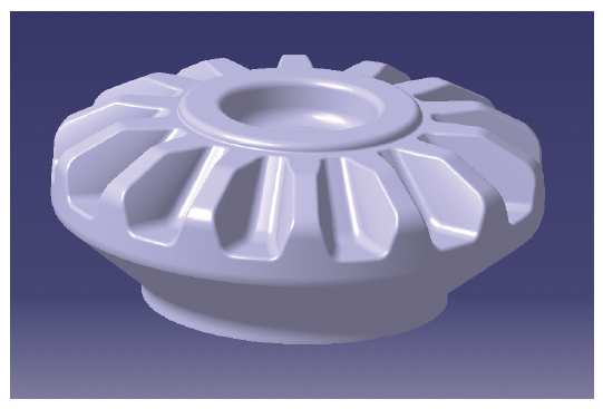
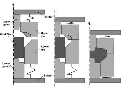
Figure 2. Process schematic – First stage, closed forging
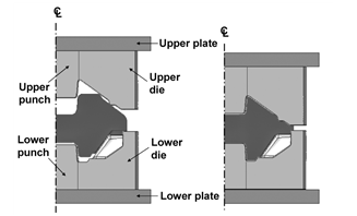
Figure 3.
Process schematic – Second stage, sizing
Bevel gear closed forging processes can be optimized through repetitive design iterations of forging simulations. The process introduced here is the final process determined after the optimization process. The material of the bevel gear is SCM420H and a saw-cut circular bar (radius 17.5 mm x height 39.0 mm) was used as the initial shape of the material.
The
process and analysis information used in the simulation of the process are as
follows.
Contact limits of die and material: 0.05 mm; About 80,000 tetrahedral elements were used; Die speeds of first stage: Figure 4; Die speeds of the second stage: -1.0 mm/s (upper die), 0.0 mm/s (lower die).
A
constant shear stress friction was used as the friction condition for the
analysis. The friction coefficient of the upper die to produce the tooth
profile was assumed to be 0.2 and the friction constant of the remaining dies
was assumed to be 0.1. It is believed that the friction of the tooth-shaped metal
die is more affected than the other metal dies because it causes a relatively
higher amount of deformation.
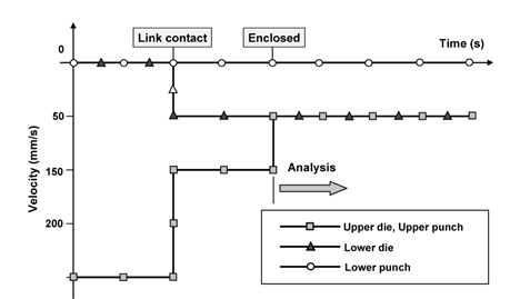
Figure 4. Velocity profile
of dies
The
developed bevel gear has 14 teeth and 28 symmetry planes, so only half of the
whole bevel gear is selected as the analysis area. Diameter and height of
initial material are 17.5 mm and 39.0 mm respectively.
Figure 5 shows the results of the optimized process analysis. In particular, it is important to emphasize that the precise description of the tooth profile is very important for obtaining accurate analysis results. As can be seen in the Figure 5, although not many tetrahedral elements were used, it can be seen that the surface triangles of the tetrahedron mesh are well depicted in the tooth profile. This point is very important in terms of reliability of analysis results.
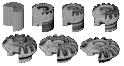
Figure
5. FE prediction of deformation
In the next blog post scheduled for next week, I will be writing further about the predictions, comparison with experiments, the machine used for experiments, quality assurance and other important details.
Do follow us on LinkedIn to stay updated and know more interesting simulation examples from a wide variety of metal forming processes.

