Enclosed die forging of an automobile differential’s bevel gear – Post 2/2
페이지 정보
작성일posted onLink
본문
Enclosed
die forging of an automobile differential’s bevel gear – Post 2/2
This article is a continuation to the earlier article - http://www.afdex.com/archive/blog/4
In this
article, we will go further into the results and discuss this approach from a
manufacturing perspective.
Just a recap of the important information.
The
material of the bevel gear is SCM420H and a saw-cut circular bar (radius 17.5
mm x height 39.0 mm) was used as the
initial shape of the material.
Contact
limits of die and material: 0.05 mm;
About
80,000 tetrahedral elements were used;
Die
speeds of the second stage: -1.0 mm/s (upper die), 0.0 mm/s (lower die).
A
constant shear stress friction was used as the friction condition for the
analysis.
The
friction coefficient of the upper die to produce the tooth profile was assumed
to be 0.2.
The
friction constant of the remaining dies was assumed to be 0.1.
The
selected target product is the bevel gear for the differential of a vehicle, as
shown in Figure 1.
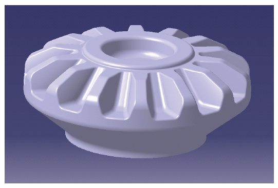
Figure 1. Bevel Gear CAD Model
Figure 2 shows the FE predictions of deformation obtained using AFDEX.
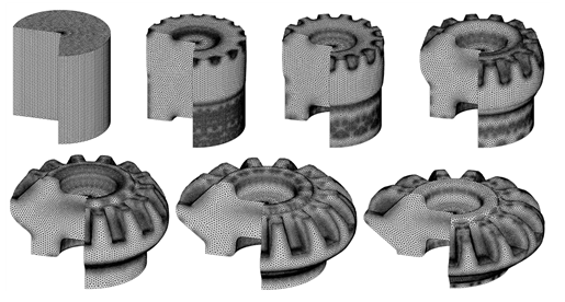
Figure 2. FE prediction of deformation
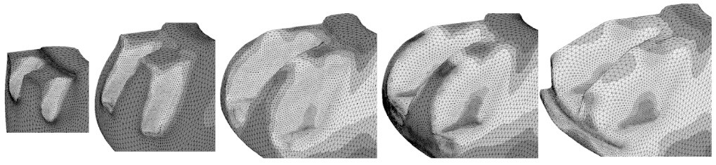
Figure 3. Predictions of tooth profile and effective strain contours
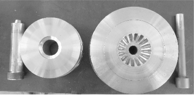
Figure 4.
Die making process (Courtesy: Jin Eng.)
The preparation of workpiece material in closed forging is also very important. Since the shape of the workpiece changes massively during closed forging, the material must be softened through a spheroidizing annealing process. If the annealing temperature is not set properly, cracks may occur in the closed forged product.
Shot peening is applied to the un-coated raw material to remove
scales, decarbonized layers and foreign substances on the surface.
For the
purpose of pilot production, the hydraulic press shown in Figure. 5 (a) and the
closing die set shown in Figure 5 (b) of Gyeongsang National University TIC was
used. This hydraulic press has specifications such as pressure capacity of
10000 kN and stroke length of 600 mm.
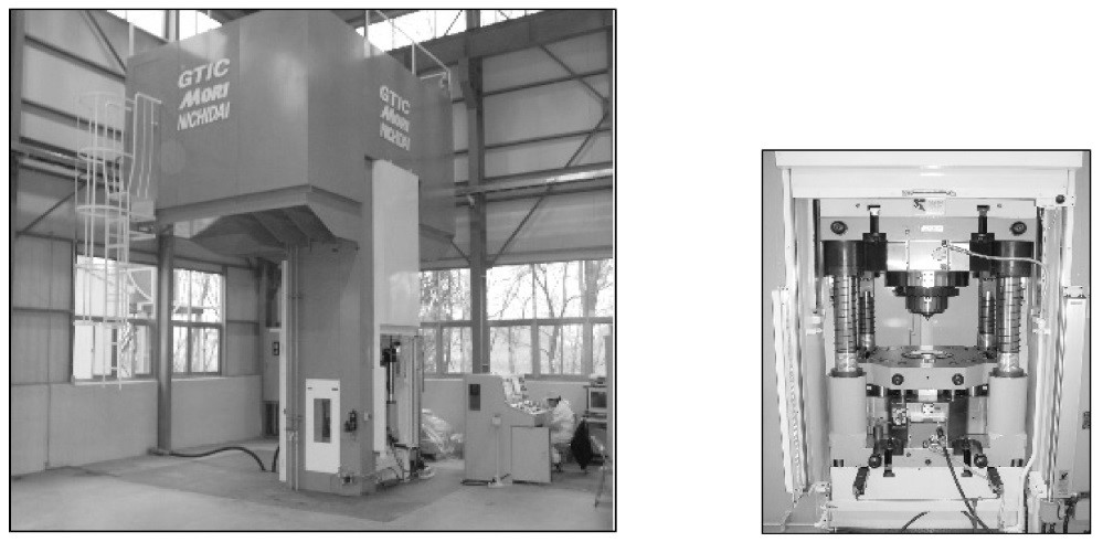
Figure 5.
Hydraulic press used for this process
Figure 6 shows the test results of the closed forging of a bevel gear produced using the above-mentioned die and equipment, and shows the deformation history of the work piece material during the forging process. As a result of the visual inspection, defective elements such as defect of lubricating film, breakage in forming state, folding, cracking, and scratching did not occur. The single pitch error, the adjacent pitch error, the cumulative pitch error, and the shaking of the groove was also checked using a bevel gear tooth tester.
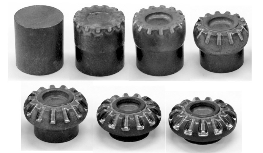
Figure 6. Closed forging experiment results of bevel gear
Quality assurance is very important in commercial development of economical bevel gears. It is essential that repetitive fabrication of the same die should be supported. The production method and the process design must be robust and efficient.
Figures
2 and 6 show that the experimental and analytical results are very
similar. That is, as a result of comparing according to the stroke distance of
the upper and lower punches, the shape of the material entering the die and the
shape of the tooth profile are very similar. In the comparison of Figure 7 (a)
and Figure 7 (b), the predicted and experimental results agree very well.

Figure 7 (a, b). Comparison of
prediction and experimental results - Forging(Left) & Sizing(Right)
Do follow us on LinkedIn to stay updated and know more interesting simulation examples from a wide variety of metal forming processes.