Finite element analysis of deep piercing process
Finite element analysis of deep piercing process
Aspect ratio, in the case of piercing in metal forming is the ratio between the thickness and the hole diameter which is usually ranges between 1.0 and 1.5. In the case of deep piercing processes, the aspect ratio goes up to 5. This is challenging from the perspective of metal forming simulation as the approach for analyzing the material separation must be robust.
Generally, there are three approaches to analyze the material separation in piercing process.
▶ Crack propagation scheme
▶ Element deletion scheme
▶ Element degradation scheme
Joun et.al (2014) proposed a new approach based on element deletion scheme after element degradation scheme which will be presented here.
Finite element analysis:
Fig. 1 shows the finite element analysis model used for analyzing the deep piercing process of which punch diameter and plate thickness are 1.2 mm and 6.0 mm, respectively, i.e., the aspect ratio is 5.0. The clearance between punch and die is 0.12 mm and that between punch and blank holder 0.01 mm. The blank holding force is 1000 N and coefficient of Coulomb friction is assumed 0.15. The blank holding force is dealt with by the force prescribing die. 2~6 times of mesh densities compared with the normal mesh density are imposed around the die corners of the punch and die. Normalized Cockcroft-Latham damage model (1996) is employed. The workpiece (AA6061) is a round blank with 16.0 mm diameter.
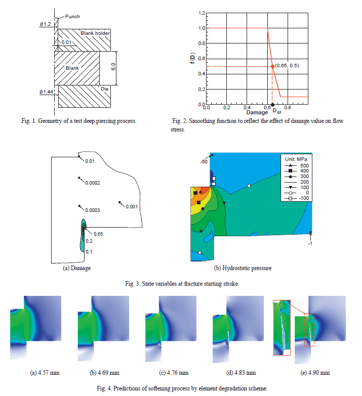
It can be observed from Fig. 3(a) that the maximum damage value at the fracture starting stroke around the lower die corner is 0.65 which was assumed as the critical damage value. Owing to the high hydrostatic pressure as shown in Fig. 3(b), the damage values at regions other than the lower die corner are negligible. Fig. 4 shows the finite element predictions obtained by the element degradation scheme. Remeshing happened 15 times during this simulation. Fig. 5 shows the comparison between the FE predictions and experiments and it can be seen that the predicted shape matches very well.
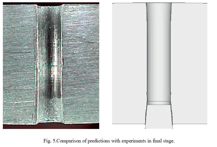
Qualitative agreement of the prediction results with experiments show that the current approach is effective. To summarize the approach, in the first stage, the simulation continues using the element degradation scheme until the shear band due to cumulative damage is formed. To degrade damaged element, flow stress of a damaged element was multiplied by an assumed smoothing function of damage value. In the second stage, element deletion scheme or crack propagation scheme is used to achieve visualization of crack or separation of pierced part. For more details, you can look into this article.
Do follow us on LinkedIn to stay updated and know more interesting simulation examples from a wide variety of metal forming processes.
Do you have any questions
about metal forming simulations?
Send us your comment, question or suggestion, or make a request.
We'll be in touch as soon as we can.
Jinju, Gyeongsangnam-do, Republic of Korea, 52818
Copyright ⓒ 2025 MFRC Co., Ltd. All Rights Reserved


